


The actual performance of any chemical process plant can be measured by only two terms, energy consumption level and on-stream/reliability factor. These are the two overall indicators of the plant performance out of which reliability factor also contributes to the energy consumption level. Hence, it becomes inevitable in an energy intensive unit like fertilizer industry, to keep a close look on this aspect of plant performance. This in turn will affect the productivity and profitability.
The expected annual energy consumption in ammonia production is of the order of 108 gigacalories in India alone that is equivalent to ~11 to 12000 MSm3 of Natural Gas or around 10 million tons of naphtha. Hence, it is most likely today to focus on proper analysis of bottlenecks & deficiencies in an existing plant while absolute analysis of technology at grass root level is also crucial with great care in its selection.
This study has been divided in four major parts, the overall loss structure, brief analysis of sectionwise losses & their remedies, losses through cooling water, and finally the role of catalysts in overall energy efficiency of the plant.
The Bares
It is only indicative to mention here the theoretical minimum requirement of energy, i.e. the thermodynamic requirement to produce one ton of ammonia is ~4.47 gigacalories. Table-1 shows the minimum requirement of various inputs per ton of ammonia.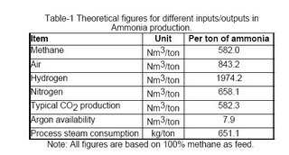
It is only indicative to mention here the theoretical minimum requirement of energy, i.e. the thermodynamic requirement to produce one ton of ammonia is ~4.47 gigacalories. Table-1 shows the minimum requirement of various inputs per ton of ammonia.

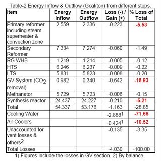
Table-2 shows the energy inputs to the different steps of ammonia production, versus energy outflow from those steps. The figures depicted in this table are for a NG based ammonia complex with conventional steam reforming process of manufacturing.
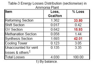
The total estimated typical losses as shown in Table-2 are of the order of 4.0 Gcal/ton of ammonia, which is around 90% of theoretical requirement, i.e. we need almost the double of thermodynamic requirement in the current trends. This indicates the need for proper energy management, analysis, monitoring, & operation for an efficient ammonia producer.
Overall Loss Structure
The losses distribution diagram as shown in Figure-1 represents the major losses in ammonia plant. Another diagram (see Figure-2 and Table-3) shows losses in terms of process efficiency at different steps.

 Obviously, the synthesis section & reforming section are the two most inefficient operations because of irreversibility of the concerned process steps involved.
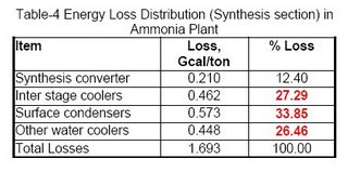
 Figures 3 & 4 (also see Table-4 & 5) for losses in synthesis & reforming sections are indicating the need of new developments in these sections, to avoid the major chunk of energy loss in cooling water.
The very first reason of ~71% of total energy loss going to the cooling water is that the low-level heat can not be recovered efficiently in absence of cooler streams. Moreover, conventional ammonia manufacturing technology does not have many margins to do so. Therefore, we are left with the option to have minimum process streams of low level energy that can be utilized for preheating cooler streams.
The second big contributor is the energy loss through surface condensers of steam turbines. For all three big compressors namely synthesis, process air & ammonia refrigeration compressor, generally steam turbines are being used in the present scenario. The condensing load of these three surface condensers is ~1.3 Gcal/ton which is ~32% of total energy losses. Therefore, it is essential now to consider some alternate drives for these compressors.
The third contributor to the higher energy consumption in an ammonia plant is the conversion efficiency of different catalytic reactors by virtue of which we have to play with bulk recycle streams. Developments towards increase in the conversion efficiency at reduced cost will make a difference in the near future.


Sectionwise Analysis
Reforming Section
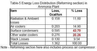
a. In the conventional process, steam reforming is done in a fired furnace heater. This increases the heat loss from reformer surface to ambient through air convection. The energy loss is predicted as around ~0.16 Gcal/ton of ammonia (Table-5). This loss however, can not be reduced economically unless the technology eliminates the use of fired furnace type primary reformers e.g. the use of GHR & CAR, where this loss is minimal (See my article - Ammonia : Steps Ahead).

a. In the conventional process, steam reforming is done in a fired furnace heater. This increases the heat loss from reformer surface to ambient through air convection. The energy loss is predicted as around ~0.16 Gcal/ton of ammonia (Table-5). This loss however, can not be reduced economically unless the technology eliminates the use of fired furnace type primary reformers e.g. the use of GHR & CAR, where this loss is minimal (See my article - Ammonia : Steps Ahead).
b. Massive amount of low level heat, from the stack of convection zone of primary reformer, is rejected into atmosphere. This loss of heat from flue gases is unavoidable because of dew point limitation of sulphur & nitrogen oxides. However, it should be lowest according to the fuel specification beyond which it is an additional loss. The same is the case with the stack of fired furnace steam super-heater.
The estimated typical design loss for a particular plant is 9.0 Gcal/hr that is equivalent to around 0.130 Gcal/ton of ammonia. Note that each 10°C reduction in stack temperature costs around ~0.012 Gcal/ton of energy. The stack losses can not be eliminated as long as fired furnace type heaters are there in existence. However, in an existing plant this can be reduced to some extent by using some energy analysis tool like pinch or exergy analysis and by considering the following options:
o Reducing the heat duty of primary reformer by shifting its load on secondary reformer up to certain optimized extent permitted by PGR unit in the back end.
o Explore the possibility of installation of new heat recovery coils.
o Explore the possibility of expanding surface area of existing coils.
o Explore the possibility of installation of new heat recovery coils.
o Explore the possibility of expanding surface area of existing coils.
The recent improvements eliminate the fired steam superheater in this section to minimize the losses due to inefficient combustion process. The high-pressure steam, generated in the ammonia plant, is now being superheated by the process gas itself downstream of the RG boiler.
c. Another Loss of ~0.2 Gcal/ton in this section is through air coolers provided to cool the treated overhead vapors of process condensate with the old system of LP stripper. This loss has been already eliminated in the newer versions of the ammonia plant by incorporating MP stripper in place of LP Stripper.
Shift Section
The water gas shift reaction is a desirable one for CO2 production, which is used as raw material for urea production. This section doesn't have any significant energy loss except through surface losses from the reactors.
CO2 Removal Section
This section of ammonia plant is the major energy consumer after cooling water system (See Table-2). This is because of the involvement of the thermally very inefficient process of distillation. This is mainly because of low-level heat dissipation at various stages of the process either in cooling water or in air coolers.
a. In this process, the solvent is recycled back after cooling for absorption. The cooler stream of GV for polishing section of the absorber is cooled in air coolers where huge amount of low level heat is dissipated in the atmosphere.
The estimated amount of energy loss is around 13.0 Gcal/hr or 0.19 Gcal/ton of ammonia. Part of this heat can be recovered by developing an appropriate scheme for an existing plant. It is estimated that around 5.0 Gcal/hr of energy can be recovered with a payback period of less than 6 months. This is equivalent to energy savings of around 0.07 Gcal/ton of ammonia. However, it can be eliminated also if a feed gas saturator is considered, which has a very good payback of ~1.5 years.
b. The second major loss in this section is through the cooling of product CO2 by cooling water. The estimated energy loss in the cooling water through CO2 is ~0.45 Gcal/ton of ammonia. This loss can not be eliminated because of low-level heat content of CO2 stream.
Synthesis Section
The major part of the losses, i.e. ~88% in this section is through the cooling water, which we are going to discuss in the next section. The remaining part is because of surface losses through the synthesis converter.
Losses Through Cooling Water
It is well known that ~71% of the total energy consumed in the conventional ammonia manufacturing process is lost through cooling water. That indicates a direct energy loss of ~2.9 Gcal/ton of ammonia. The break-up of this energy loss is given in Table-2.
It is well known that ~71% of the total energy consumed in the conventional ammonia manufacturing process is lost through cooling water. That indicates a direct energy loss of ~2.9 Gcal/ton of ammonia. The break-up of this energy loss is given in Table-2.
The major contributor to this 2.9 Gcal/ton of energy loss is through the surface condensers of three major compressors, which have a cooling load of ~1.3 Gcal/ton of ammonia. Therefore, an alternate option is needed either for compression method or for reduced steam input or the minimal use of condensing type turbines.
The use of gas turbine, in place of steam turbine, for process air compressor in the new plants is an effective way to reduce these losses to some extent. However, this device can not be used for all compressors because of total steam balance in the complex and especially for the synthesis compressor. However, the surface condenser losses for the ammonia compressor can be compared based on the economic viability of vapor absorption refrigeration cycle vs. mechanical refrigeration cycle. If it becomes economically feasible then the total saving of ~0.4 Gcal/ton can be obtained including ~0.3 Gcal/ton from process air compressor on gas turbine.
Another contributor to energy loss in this category is the use of interstage coolers of compressors. This loss through inter coolers is of the order of ~0.64 Gcal/ton of ammonia out of which ~0.46 Gcal/ton is through the synthesis compressor alone, i.e. ~72% of all interstage coolers. This loss, however, will not be eliminated unless the compression device is changed, but it can be thought of to recover this energy by process streams e.g. condensate stream before treatment as feed preheating. Nevertheless, the overall system does also require the cooling water, as during start-up these process streams will not be available.
Role of Catalyst
The performance of catalysts employed in the plant is the major factor towards overall energy efficiency of any process plant and should be considered as and when new high conversion efficiency catalysts come to the market. The catalyst activity is the property by virtue of which we have to play with bulk recycle streams; consequently, it leads to recurring expenditure on energy cost. If full replacement of any catalyst is not permitted then we should consider an optimum blend of high activity catalyst & cheaper catalyst. The higher energy cost today has completely changed the scenario of options, which were not supposed to be considered in the 1980's or 1990's.
The performance of catalysts employed in the plant is the major factor towards overall energy efficiency of any process plant and should be considered as and when new high conversion efficiency catalysts come to the market. The catalyst activity is the property by virtue of which we have to play with bulk recycle streams; consequently, it leads to recurring expenditure on energy cost. If full replacement of any catalyst is not permitted then we should consider an optimum blend of high activity catalyst & cheaper catalyst. The higher energy cost today has completely changed the scenario of options, which were not supposed to be considered in the 1980's or 1990's.
Conclusion
Finally, it is the manufacturer who has to decide his limit of investment & limit of his returns. One should be careful in analyzing isolated options because one option combined with the other may be more useful & economical than both separately. Moreover, at times the effect of one option on the other may be negative as both of them serve in the same direction particularly when the plant is operating at its peak level of capacity. Hence, this is the right time for each manufacturer to look into his process again, for identifying potential energy savers using robust tools of energy audit.
Finally, it is the manufacturer who has to decide his limit of investment & limit of his returns. One should be careful in analyzing isolated options because one option combined with the other may be more useful & economical than both separately. Moreover, at times the effect of one option on the other may be negative as both of them serve in the same direction particularly when the plant is operating at its peak level of capacity. Hence, this is the right time for each manufacturer to look into his process again, for identifying potential energy savers using robust tools of energy audit.


3 comments:
hi, can you provide reference to above data...that shall be highly helpful for my project.
Thanks in anticipation.
Vaibhav
This data is from actual operation of one of the Ammonia plant However I can not disclose the source.
Amazing amount of great, actionable advice. I will keep coming back to this for a while to try and implement many of these! Thanks!
Post a Comment